
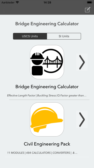
Bridge Engineering Calculator
Calculate parameters instantly
V PUGAZHENTHI
iPhone Screenshots


iPad Screenshots


Description
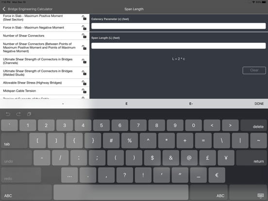
Calculate , suspension cable, and civil parameters with 58 specialized tools. Input values and units to get automatic results. Switch between metric and imperial units.
Bridge Engineering Calculator contains 58 calculators, to calculate different bridge, suspension cable and civil engineering parameters. Automatic & accurate calculations with every unit and value changes.
* Available in Metric(SI) and Imperial Units *
* Available in English, Français, Español, Italiano, Deutsch & Português *
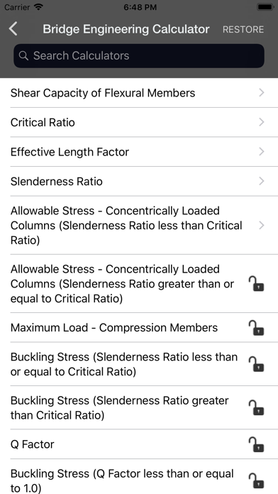
Bridge Engineering Calculator contains following 58 Calculators:
• Shear Capacity of Flexural Members
• Critical Ratio
• Effective Length Factor
• Slenderness Ratio
• Allowable Stress - Concentrically Loaded Columns (Slenderness Ratio (lesser) Critical Ratio)
• Allowable Stress - Concentrically Loaded Columns (Slenderness Ratio (greater=) Critical Ratio)
• Maximum Load - Compression Members
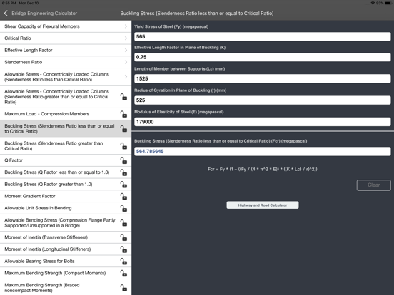
• Buckling Stress (Slenderness Ratio lesser= Critical Ratio)
• Buckling Stress (Slenderness Ratio greater Critical Ratio)
• Q Factor
• Buckling Stress (Q Factor lesser= 1)
• Buckling Stress (Q Factor greater 1)
• Moment Gradient Factor
• Allowable Unit Stress in Bending
• Allowable Bending Stress (Compression Flange Partly Supported/Unsupported in a Bridge)
• Moment of Inertia (Transverse Stiffeners)
• Moment of Inertia (Longitudinal Stiffeners)
• Allowable Bearing Stress for Bolts
• Maximum Bending Strength (Compact Moments)
• Maximum Bending Strength (Braced noncompact Moments)
• Minimum Flange Thickness (Compact Moments)
• Minimum Flange Thickness (Braced noncompact Moments)
• Minimum Web Thickness (Compact Moments)
• Minimum Web Thickness (Braced noncompact Moments)
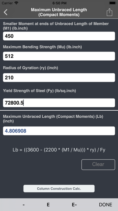
• Maximum Unbraced Length (Compact Moments)
• Maximum Unbraced Length (Braced noncompact Moments)
• Allowable Bearing Stress (Milled Stiffeners)
• Allowable Stress - Rollers and Rockers (Roller/Rocker Diameter lesser 25)
• Allowable Stress - Rollers and Rockers (Roller/Rocker Diameter greater= 25)
• Allowable Bearing Stress on Pins subject to Rotation
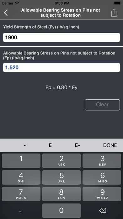
• Allowable Bearing Stress on Pins not subject to Rotation
• Unit Stress in Steel (Unshored Members)
• Unit Stress in Steel (Shored Members)
• Horizontal Shear Range at the Juncture of Slab and Beam
• Horizontal Shear (Allowable Range) - Channels with Fillet Welds
• Horizontal Shear (Allowable Range) - Welded Studs
• Force in Slab - Maximum Positive Moment (Concrete Section)
• Force in Slab - Maximum Positive Moment (Steel Section)
• Force in Slab - Maximum Negative Moment
• Number of Shear Connectors
• Number of Shear Connectors (Between Points of Maximum Positive Moment and Points of Maximum Negative Moment)
• Ultimate Shear Strength of Connectors in Bridges (Channels)
• Ultimate Shear Strength of Connectors in Bridges (Welded Studs)
• Allowable Shear Stress (Highway Bridges)
• Midspan Cable Tension
• Tension at Supports of the Cable
• Cable Length
• Catenary Parameter
• Catenary Cable Sag Distance
• Span Length
• Tension at any point
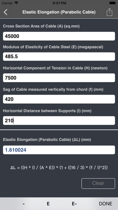
• Elastic Elongation (Parabolic Cable)
• Change in Sag
• Initial Shape of Cable
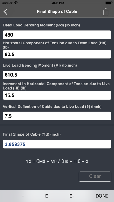
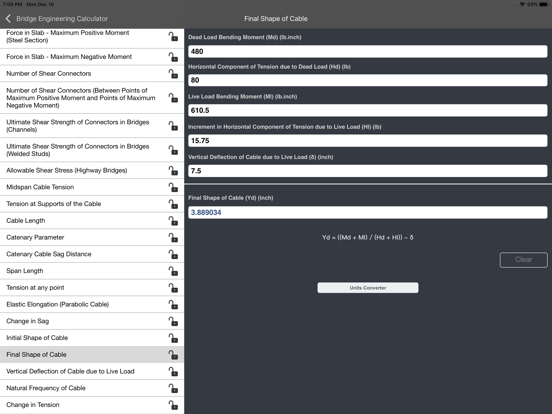
• Final Shape of Cable
• Vertical Deflection of Cable due to Live Load
• Natural Frequency of Cable
• Change in Tension
Key Features:
• Complete coverage of calculators in bridge, suspension cable and civil engineering parameters.
• Automatic calculation of the output with respect to changes in the input, output and units.
• Formulas are provided for each calculator.
Most Comprehensive Bridge and Suspension Cable Calculator
App information from Apple App Store. Bridge Engineering Calculator and related trademarks belong to V PUGAZHENTHI.